-
2103 غرفة رقم 322 طريق شينغغانغ ون، منطقة هايكانغ، شيامن فوجيان، الصين


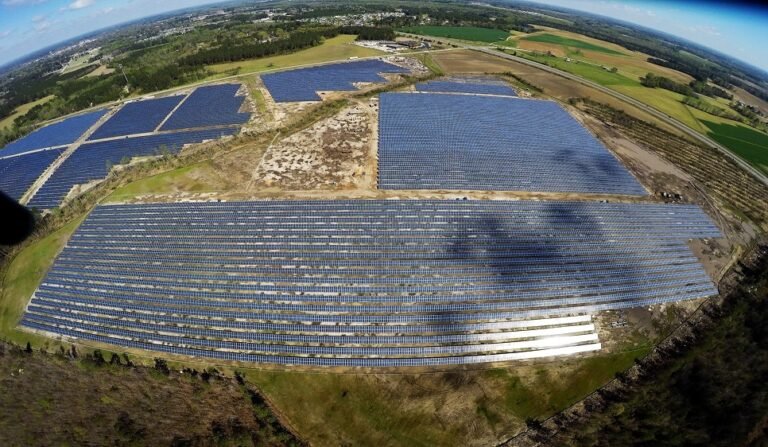
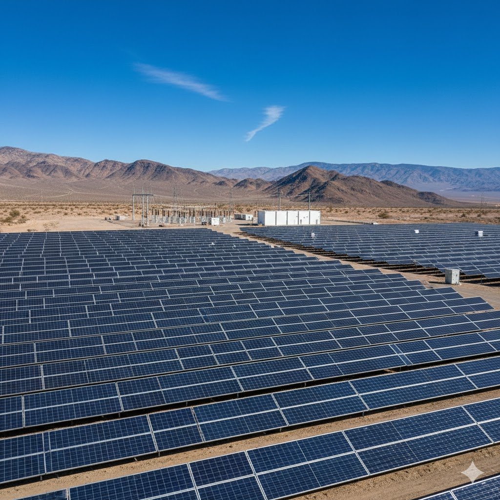
5MW Solar Roof Mounting Project Construction Organization Design
Table of Contents
Project Overview and Characteristics
1. Basic Project Information
- Installed Capacity: 5MW (divided into three grid connection points of 2MW, 2MW, and 1MW)
- Installation Location: Industrial park rooftops (approximately 80% metal roofing and 20% concrete roofing), with a usable area of about 52,000 m²
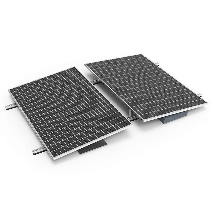
- Module Type: 550W monocrystalline bifacial modules (9,100 units), with a tilt angle of 10°–15°
- Inverter Configuration: String inverters (50kW × 90 units)
2. Key Challenges
- Decentralized rooftops and complex ownership: Requires coordination among five different property owners.
- Reinforcement and waterproofing of metal roofing
- Grid connection: Must align with the power utility’s approval process for connection points.
Overall Deployment and Objectives
1. Organizational Structure
- Project Management Office: Includes one project manager, one technical lead, and one safety supervisor.
- Construction Teams: Divided into three working groups (module installation team, electrical construction team, and commissioning support team).
2. Key Milestone Targets
| Phase | Duration | Deliverables |
|---|---|---|
| Start-up Prep | 10 days | Construction plan approval, materials entry filing completed |
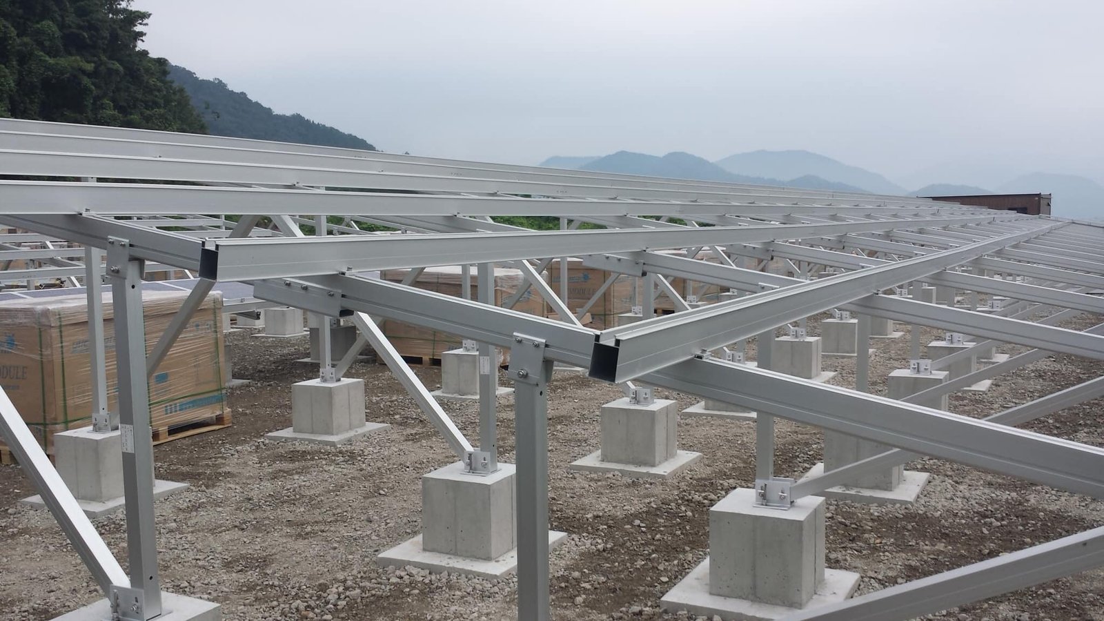
| Foundation Work | 25 days | Rooftop reinforcement completed, bracket bases embedded |
| Bracket & Module Installation | 45 days | All modules installed, tilt angle error ≤ 1° |
| Electrical Work | 30 days | DC-side insulation resistance > 1MΩ |
| Grid Connection Acceptance | 15 days | Approved by the utility company for grid connection |
3. Construction Master Plan Layout
- Materials Storage Area: Includes a temporary shelter for modules (protected from rain and dust) and a cable reel storage zone.
- Fabrication Area: Dedicated space for bracket cutting and welding (with dust removal equipment).
- Temporary Power Supply: Three 250kVA box-type transformers connected to the owner’s low-voltage distribution cabinet.

Construction Plan by Sub-Project
1. Rooftop Structural Treatment
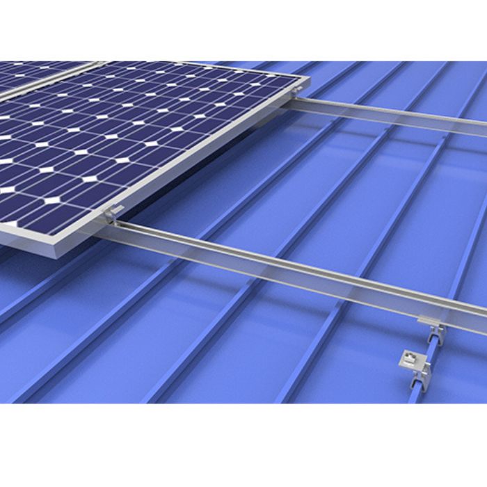
- Metal Roof Reinforcement:
- Utilize specialized roof clamps (model “CT-3”) to fix the support brackets, arranged at 1.5m intervals along each purlin span.
- For areas showing signs of rust, apply an epoxy zinc-rich primer (thickness ≥ 80µm).
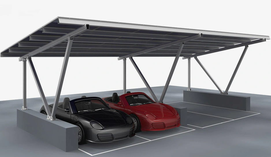
- Concrete Roof Waterproofing:
- Embed chemical anchor bolts and then apply polyurethane waterproof coating (thickness 2mm, elongation ≥ 450%).
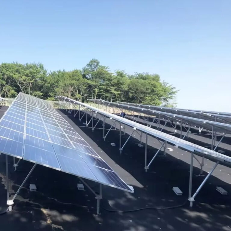
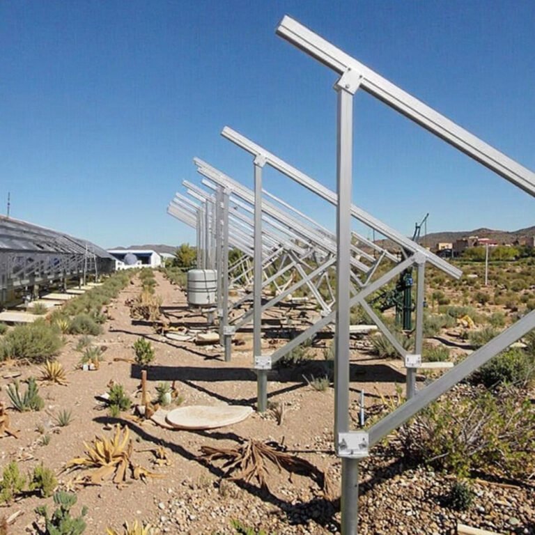
2. Support Brackets and Module Installation
- Bracket Installation:
- Tolerance Control: Vertical deviation of columns ≤ 3mm/m; horizontal beam spacing deviation ±5mm.
- Grounding for Lightning Protection: Use 40×4mm galvanized flat steel with continuous welding (ground resistance ≤ 4Ω).
- Module Installation:
- Fixed using mechanical clamps, with horizontal/vertical spacing deviations ≤ 2mm.
- Important: Avoid stepping on the metal roof’s raised wave crests (workers may only walk in the wave troughs).
3. Electrical System Construction
- DC Side Construction:
- String Design: 22 modules per string (22 × 550W = 12.1kW), each inverter connects 9–10 strings.
- Cable Selection: PV1-F 4mm² photovoltaic cable (UV-resistant, operating temperature from –40°C to 120°C).
- AC Side and Grid Connection:
- Each inverter’s AC output is fitted with a surge protector (Iimp ≥ 15kA).
- The grid connection cabinet includes anti-islanding protection and an online power quality monitoring device.
Resource Allocation Plan
1. Workforce Plan (Peak Period)
| Role | Headcount | Scope of Work |
|---|---|---|
| Bracket Installers | 30 people | Bracket measurement, cutting, and reinforcement |
| Module Installers | 40 people | Module handling, leveling, and mounting |
| Electricians | 15 people | DC wiring, inverter installation and commissioning |
| General Laborers | 20 people | Materials handling, safety supervision |
2. Machinery and Equipment List
| Equipment Name | Model/Specification | Quantity |
|---|---|---|
| Articulated Aerial Work Platform | GTZZ18 (18m) | 3 units |
| Specialized PV Clamp Tool | YKJ-5 | 10 units |
| DC Insulation Tester | Fluke 1507 | 5 units |
| Laser Level | Leica LINO L2 | 6 units |
3. Materials Delivery Plan
- First Batch (5 days after project start): Steel for brackets, chemical anchor bolts, and grounding flat steel.
- Second Batch (20 days after project start): Photovoltaic modules, inverters, and DC cables.
- Third Batch (50 days after project start): Grid connection cabinet and monitoring system equipment.
Quality and Safety Management
1. Quality Standards
- Mandatory National Codes:
- Code for Construction of Photovoltaic Power Station (GB 50794-2012)
- Code for Design of Lightning Protection of Buildings (GB 50057-2010)
- Key Performance Indicators:
- String current dispersion ≤ 3% (sample-check 10% with I-V curve tester).
- Maximum roof membrane deformation ≤ 5mm (observed 72 hours after completion).
2. Safety Management Measures
- Control of High-Risk Operations:
- Work at Height: 100% use of double-hook safety harnesses (lifelines installed on rooftop).
- Hoisting Operations: Demarcate a restricted area; signal operators must be certified.
- Emergency Preparedness:
- Heatstroke Treatment: Provide Huoxiang Zhengqi liquid and sunshades on site (no outdoor work from 11:00–15:00 on high-temperature days).
- Electrical Fire: Equip each work area with two 5kg dry powder fire extinguishers.
Progress Assurance Measures
1. Dynamic Adjustment Mechanism
- Daily Morning Meeting: Summarize previous day’s progress deviation and adjust priorities for the current day’s tasks.
- Weather Alerts: Obtain weather forecasts three days in advance; shift to indoor electrical wiring on rainy days.
2. Schedule Optimization Strategies
- Parallel Construction: Execute rooftop reinforcement and pre-assembly of brackets simultaneously (pre-assembly ratio up to 60%).
- Modular Transportation: Transport modules by string sets to reduce on-site sorting time.

Acceptance and Handover
1. Staged Acceptance
| Acceptance Stage | Participants | Document Package |
|---|---|---|
| Hidden Works Acceptance | Owner / Supervisor / Constructor | Waterproof layer inspection report, ground resistance test |
| Pre-Grid Connection Acceptance | Utility Company / Third-Party Testing Agency | Anti-islanding test report, power quality report |
2. Warranty Services
- Module Warranty: 12-year product warranty; performance degradation ≤ 20% over 25 years.
- Intelligent O&M: Deploy a monitoring platform (automatic fault dispatch, 2-hour response time).
References:
- Construction Master Plan Layout
- Rooftop Load Calculation (including structural institute approval)
- Grid Connection Electrical Diagram
Note: This plan should be adjusted based on the actual rooftop survey results (e.g., metal roof thickness, purlin spacing). If necessary, commission a third party to conduct load-bearing reviews.