-
2103 Δωμάτιο NO.322 Xinggang One Road, Haicang District, Xiamen Fujian, Κίνα

Photovoltaic (PV) Structural Design: A Comprehensive Guide to the End-to-End Mounting System Process
In a solar power project, the mounting system may seem like a “supporting actor,” but it is actually the backbone that supports the modules, ensures safety, and maximizes energy yield. For industry professionals, poor design leads to micro-cracks in modules and power loss; at worst, it causes structural collapse and catastrophic financial failure.
This guide breaks down the professional design workflow—from initial environmental assessment to structural calculation and final verification—to ensure your project is reliable, bankable, and built to last.
Table of Contents
I. Preliminary Preparation: Mastering Site Conditions to Prevent Design Deviations
Expert design begins with data, not drawings. The core logic of a mounting system is “site-specific adaptation.” We focus on three critical dimensions:
1. Scenario and Environmental Analysis
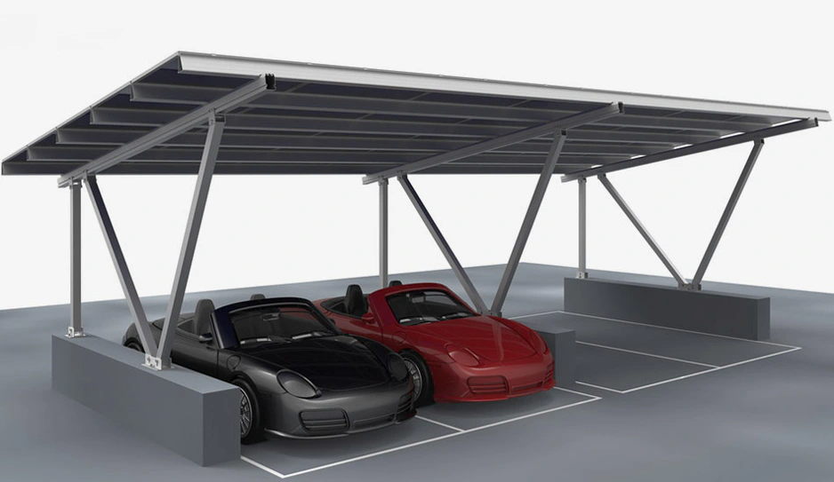
- Project Type: Is it ground-mounted, rooftop (flat/pitched), floating PV, or BIPV? Each requires a fundamentally different logic for drainage, land clearing, or load distribution.
- Environmental Loads: We collect high-precision data on:
- Wind Load: Local basic wind pressure, gust coefficients, and topographic factors (coastal vs. mountainous).
- Snow Load: Maximum snow depth and density, including freeze-thaw cycles.
- Seismic Rating: Earthquake intensity parameters for structural resilience.
- Corrosion Factors: Salt spray (coastal), high humidity, or sandstorms (desert) dictate material and coating selection.
2. Module Specifications and System Requirements
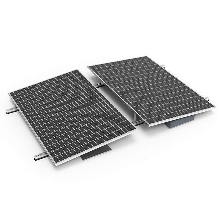
The bracket serves the module. We confirm dimensions, weight, and orientation (Portrait vs. Landscape). High-power modules (182mm/210mm) are heavier and have larger surface areas, requiring higher purlin strength and specific clamping zones.
3. Geological and Civil Surveys
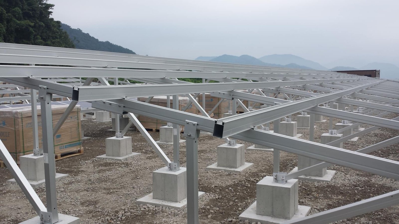
For ground projects, we analyze soil bearing capacity and groundwater levels to choose between concrete strips, helical piles, or rammed posts. For rooftops, we audit the original structural drawings to calculate residual load capacity and ensure waterproofing integrity.

II. Conceptual Design: Balancing Performance with Cost-Efficiency
Once the data is set, we move to the solution phase. Our goal is to maximize ROI by balancing safety with material economy.
- Structural Selection: We choose between Fixed-Tilt (low maintenance, cost-effective) and Tracking Systems (10-20% yield increase). Material choice—Aluminum Alloy (lightweight, corrosion-resistant for roofs) or Steel (high strength, cost-effective for large-scale)—is optimized for the site.
- Parameter Optimization: We use software simulation (e.g., PVSyst) to determine the optimal tilt angle for maximum irradiation, while calculating row spacing to eliminate inter-row shading during winter solstices.
- Foundation Engineering: Selecting the “roots” of the system. Whether it’s a ballasted system for non-penetrative roof mounts or specialized piles for soft soil, the foundation is engineered for long-term stability.
III. Structural Calculation: Protecting the “Safety Bottom Line”
We don’t “guesstimate” safety. Our engineers use professional software (PKPM, SAP2000, ANSYS) to perform rigorous checks based on international standards (e.g., AS/NZS 1170, Eurocode, or GB standards).
- Load Combination Analysis: We simulate the “worst-case scenarios” by combining dead loads (weight), live loads (maintenance), wind loads (uplift and pressure), and snow/seismic loads.
- Component Stability: We verify the bending, shearing, and buckling strength of every post, purlin, and brace.
- Connection Node Audits: Nodes are often the weakest links. We perform detailed checks on bolt shear, clamp tension, and anti-slip resistance to prevent local failures from cascading into a total collapse.
IV. Detailed Engineering & Technical Disclosure: Bringing Design to Life
A design is only as good as its execution. We provide:
- Comprehensive Blueprints: Precise component dimensions, node details, and foundation layouts.
- Technical Disclosure: We provide construction units with specific torque requirements for bolts, installation tolerances, and anti-corrosion coating procedures.
- Detail Orientation: For example, specifying exact tightening torques ensures that joints don’t loosen over time due to vibration while avoiding damage to the structural members from over-tightening.
V. Verification and Optimization: Closing the Quality Loop
Our commitment continues after the design is delivered:
- On-site Inspection: We verify installation accuracy and coating thickness (using ultrasonic gauges) to ensure the physical build matches the digital twin.
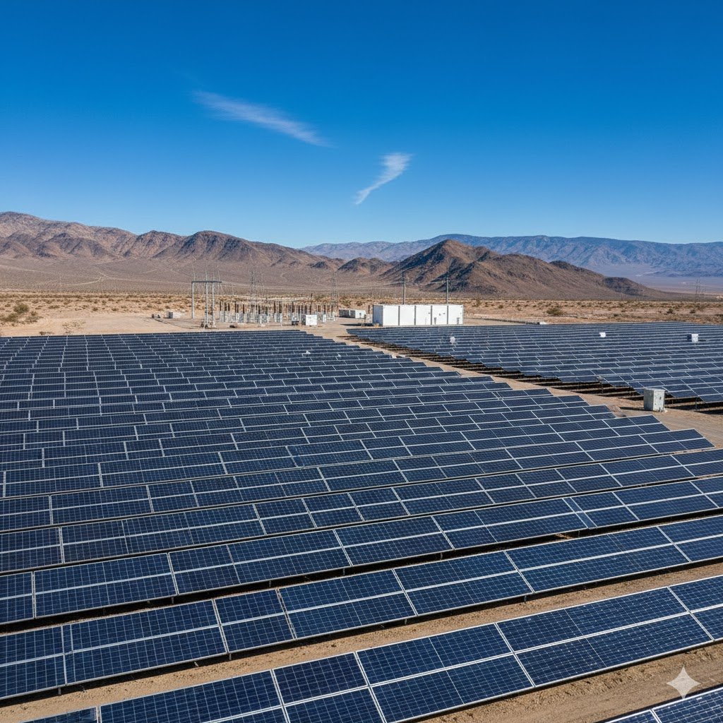
- Long-term Monitoring: For utility-scale projects, we monitor structural deformation under actual environmental stress to refine and optimize future iterations.
The Verdict: Design is the Art of Balance
In PV mounting systems, the goal isn’t just “strength”—it is the perfect equilibrium between safety, cost-efficiency, and ease of installation. By following a rigorous, closed-loop design process, we eliminate hidden risks and ensure your solar assets perform for their intended 25+ year lifespan.