-
2103 Room NO.322 Xinggang One Road,Haicang District,Xiamen Fujian,China


5MW Solar Roof Mounting Project Construction Organization Design
Table of Contents
Project Overview and Characteristics
1. Basic Project Information
- Installed Capacity: 5MW (divided into three grid connection points of 2MW, 2MW, and 1MW)
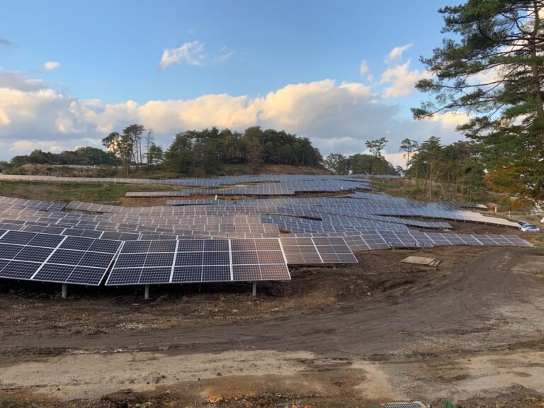
- Installation Location: Industrial park rooftops (approximately 80% metal roofing and 20% concrete roofing), with a usable area of about 52,000 m²
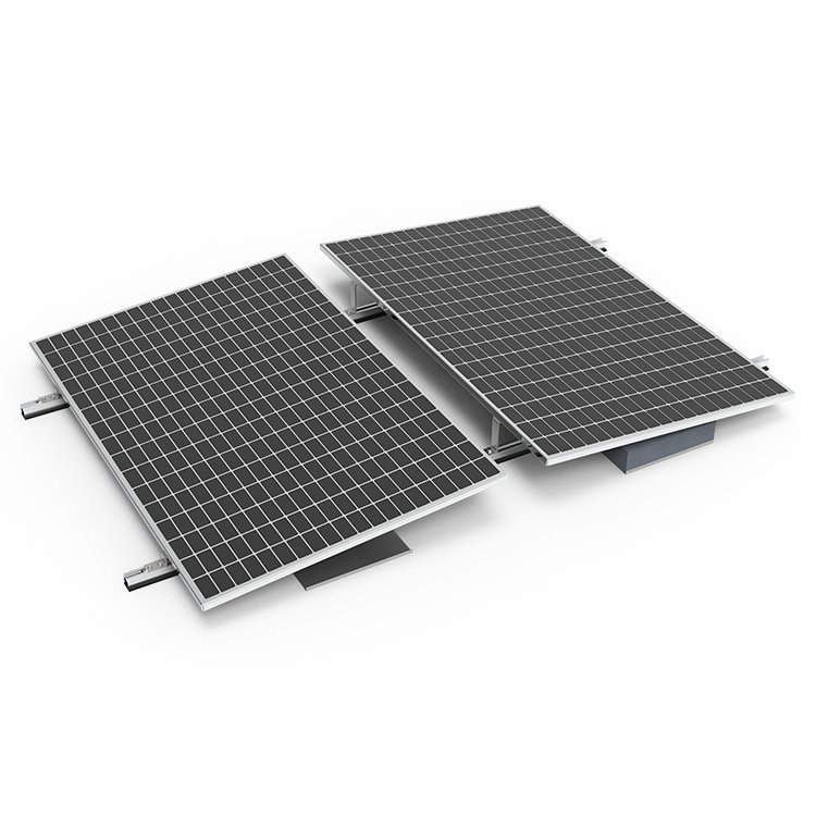
- Module Type: 550W monocrystalline bifacial modules (9,100 units), with a tilt angle of 10°–15°
- Inverter Configuration: String inverters (50kW × 90 units)
2. Key Challenges
- Decentralized rooftops and complex ownership: Requires coordination among five different property owners.
- Reinforcement and waterproofing of metal roofing
- Grid connection: Must align with the power utility’s approval process for connection points.
Overall Deployment and Objectives
1. Organizational Structure
- Project Management Office: Includes one project manager, one technical lead, and one safety supervisor.
- Construction Teams: Divided into three working groups (module installation team, electrical construction team, and commissioning support team).
2. Key Milestone Targets
| Phase | Duration | Deliverables |
|---|---|---|
| Start-up Prep | 10 days | Construction plan approval, materials entry filing completed |
| Foundation Work | 25 days | Rooftop reinforcement completed, bracket bases embedded |
| Bracket & Module Installation | 45 days | All modules installed, tilt angle error ≤ 1° |
| Electrical Work | 30 days | DC-side insulation resistance > 1MΩ |
| Grid Connection Acceptance | 15 days | Approved by the utility company for grid connection |
3. Construction Master Plan Layout
- Materials Storage Area: Includes a temporary shelter for modules (protected from rain and dust) and a cable reel storage zone.
- Fabrication Area: Dedicated space for bracket cutting and welding (with dust removal equipment).
- Temporary Power Supply: Three 250kVA box-type transformers connected to the owner’s low-voltage distribution cabinet.

Construction Plan by Sub-Project
1. Rooftop Structural Treatment
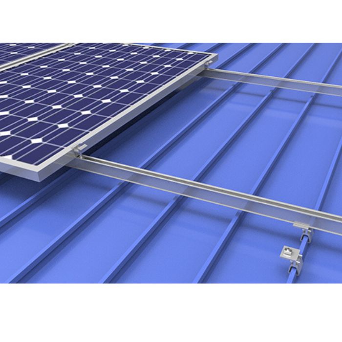
- Metal Roof Reinforcement:
- Utilize specialized roof clamps (model “CT-3”) to fix the support brackets, arranged at 1.5m intervals along each purlin span.
- For areas showing signs of rust, apply an epoxy zinc-rich primer (thickness ≥ 80µm).
- Concrete Roof Waterproofing:
- Embed chemical anchor bolts and then apply polyurethane waterproof coating (thickness 2mm, elongation ≥ 450%).
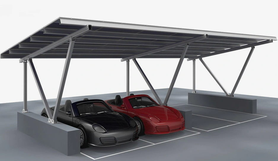
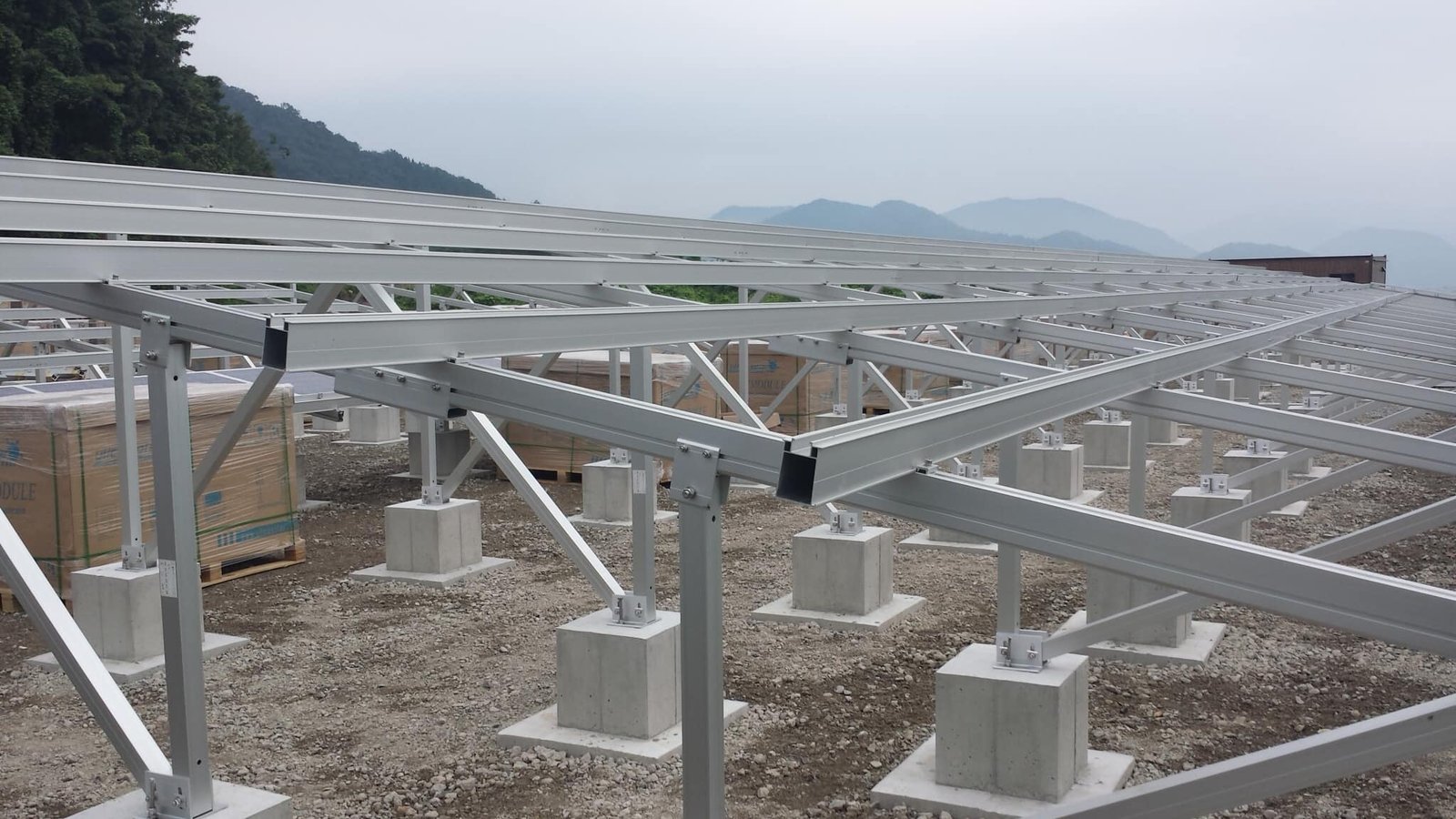
2. Support Brackets and Module Installation
- Bracket Installation:
- Tolerance Control: Vertical deviation of columns ≤ 3mm/m; horizontal beam spacing deviation ±5mm.
- Grounding for Lightning Protection: Use 40×4mm galvanized flat steel with continuous welding (ground resistance ≤ 4Ω).
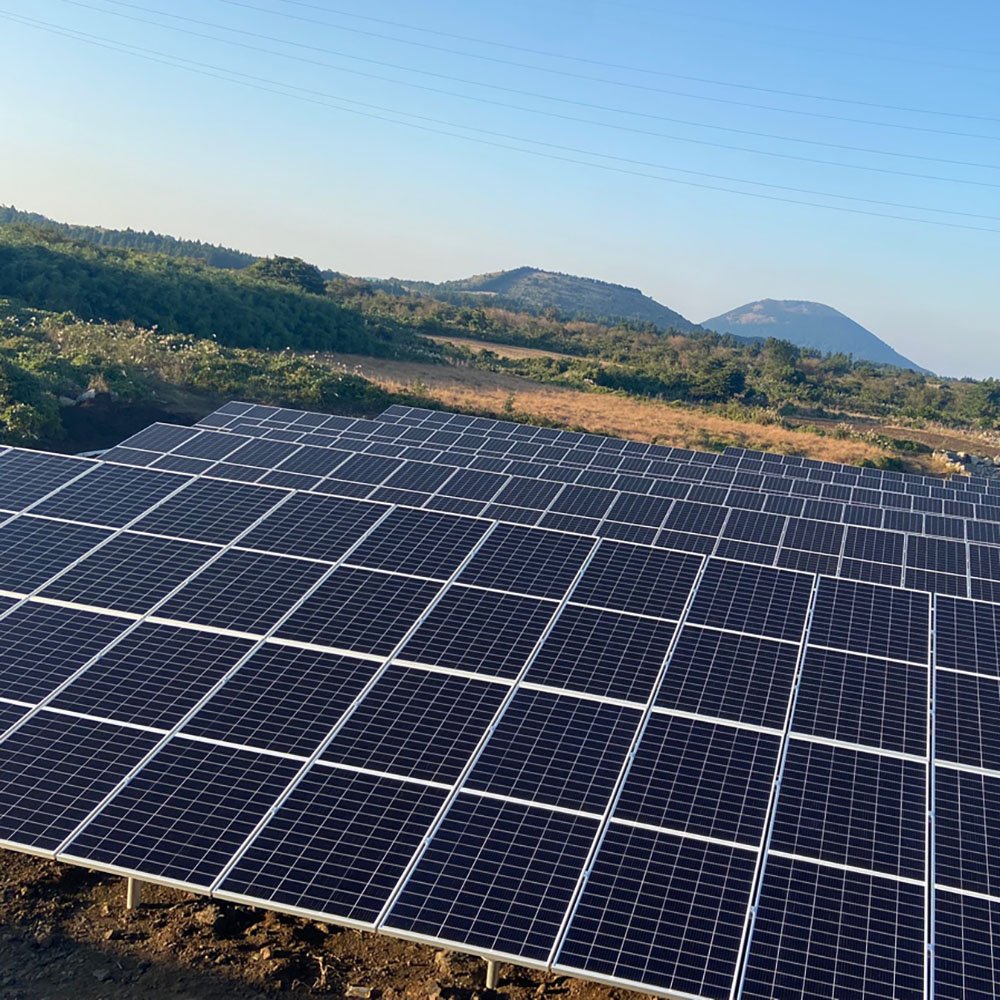
- Module Installation:
- Fixed using mechanical clamps, with horizontal/vertical spacing deviations ≤ 2mm.
- Important: Avoid stepping on the metal roof’s raised wave crests (workers may only walk in the wave troughs).
3. Electrical System Construction
- DC Side Construction:
- String Design: 22 modules per string (22 × 550W = 12.1kW), each inverter connects 9–10 strings.
- Cable Selection: PV1-F 4mm² photovoltaic cable (UV-resistant, operating temperature from –40°C to 120°C).
- AC Side and Grid Connection:
- Each inverter’s AC output is fitted with a surge protector (Iimp ≥ 15kA).
- The grid connection cabinet includes anti-islanding protection and an online power quality monitoring device.
Resource Allocation Plan
1. Workforce Plan (Peak Period)
| Role | Headcount | Scope of Work |
|---|---|---|
| Bracket Installers | 30 people | Bracket measurement, cutting, and reinforcement |
| Module Installers | 40 people | Module handling, leveling, and mounting |
| Electricians | 15 people | DC wiring, inverter installation and commissioning |
| General Laborers | 20 people | Materials handling, safety supervision |
2. Machinery and Equipment List
| Equipment Name | Model/Specification | Quantity |
|---|---|---|
| Articulated Aerial Work Platform | GTZZ18 (18m) | 3 units |
| Specialized PV Clamp Tool | YKJ-5 | 10 units |
| DC Insulation Tester | Fluke 1507 | 5 units |
| Laser Level | Leica LINO L2 | 6 units |
3. Materials Delivery Plan
- First Batch (5 days after project start): Steel for brackets, chemical anchor bolts, and grounding flat steel.
- Second Batch (20 days after project start): Photovoltaic modules, inverters, and DC cables.
- Third Batch (50 days after project start): Grid connection cabinet and monitoring system equipment.
Quality and Safety Management
1. Quality Standards
- Mandatory National Codes:
- Code for Construction of Photovoltaic Power Station (GB 50794-2012)
- Code for Design of Lightning Protection of Buildings (GB 50057-2010)
- Key Performance Indicators:
- String current dispersion ≤ 3% (sample-check 10% with I-V curve tester).
- Maximum roof membrane deformation ≤ 5mm (observed 72 hours after completion).
2. Safety Management Measures
- Control of High-Risk Operations:
- Work at Height: 100% use of double-hook safety harnesses (lifelines installed on rooftop).
- Hoisting Operations: Demarcate a restricted area; signal operators must be certified.
- Emergency Preparedness:
- Heatstroke Treatment: Provide Huoxiang Zhengqi liquid and sunshades on site (no outdoor work from 11:00–15:00 on high-temperature days).
- Electrical Fire: Equip each work area with two 5kg dry powder fire extinguishers.
Progress Assurance Measures
1. Dynamic Adjustment Mechanism
- Daily Morning Meeting: Summarize previous day’s progress deviation and adjust priorities for the current day’s tasks.
- Weather Alerts: Obtain weather forecasts three days in advance; shift to indoor electrical wiring on rainy days.
2. Schedule Optimization Strategies
- Parallel Construction: Execute rooftop reinforcement and pre-assembly of brackets simultaneously (pre-assembly ratio up to 60%).
- Modular Transportation: Transport modules by string sets to reduce on-site sorting time.

Acceptance and Handover
1. Staged Acceptance
| Acceptance Stage | Participants | Document Package |
|---|---|---|
| Hidden Works Acceptance | Owner / Supervisor / Constructor | Waterproof layer inspection report, ground resistance test |
| Pre-Grid Connection Acceptance | Utility Company / Third-Party Testing Agency | Anti-islanding test report, power quality report |
2. Warranty Services
- Module Warranty: 12-year product warranty; performance degradation ≤ 20% over 25 years.
- Intelligent O&M: Deploy a monitoring platform (automatic fault dispatch, 2-hour response time).
References:
- Construction Master Plan Layout
- Rooftop Load Calculation (including structural institute approval)
- Grid Connection Electrical Diagram
Note: This plan should be adjusted based on the actual rooftop survey results (e.g., metal roof thickness, purlin spacing). If necessary, commission a third party to conduct load-bearing reviews.