-
2103 Room NO.322 Xinggang One Road, Haicang District, Xiamen Fujian, China


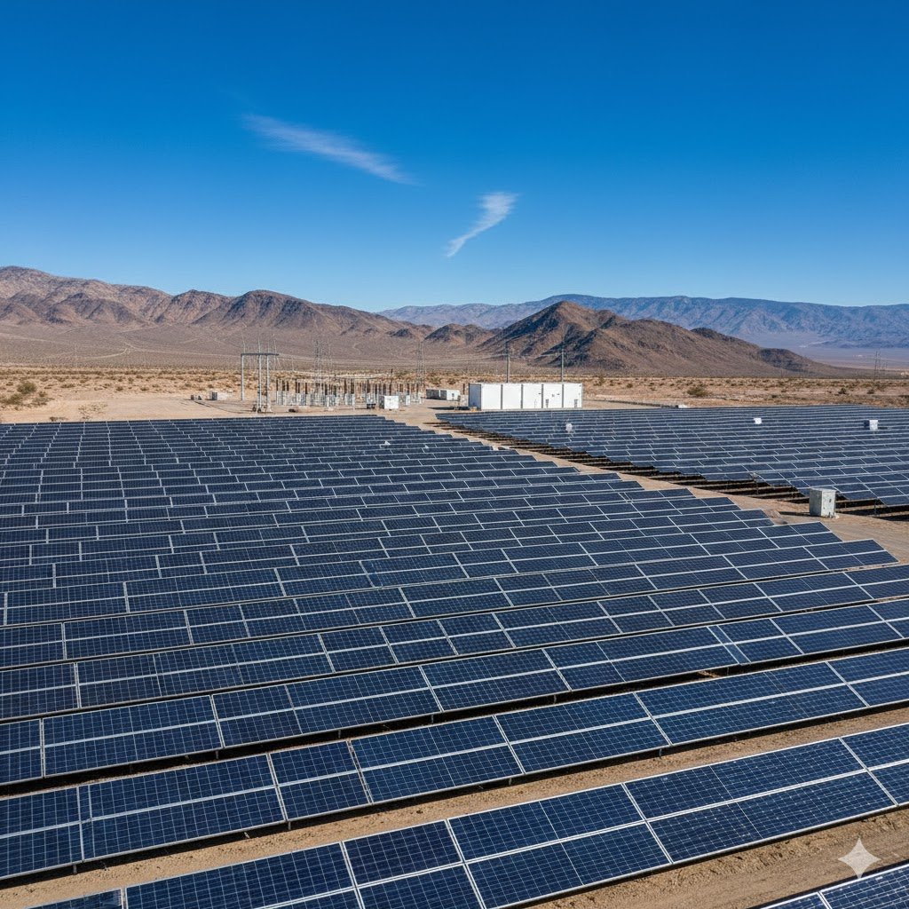
Solar Mounting System Structural Calculation Report
Project Name: XX Distributed Photovoltaic Project
Design Unit: XX New Energy Technology Co., Ltd.
Date: XX Month, 2025
1. Design Basis
- “Photovoltaic Power Station Design Code” (GB 50797-2012)
- “Steel Structure Design Standard” (GB 50017-2017)
- Local wind pressure and snow pressure data (from XX meteorological station)
- Component Parameters: Monocrystalline silicon 550W, dimensions 2278×1134×30mm, weight 28.5kg/piece
2. Foundation Parameters
2.1 Environmental Condition Parameters
| Parameter | Value | Note |
|---|---|---|
| Local Wind Pressure | 0.45 kN/m² | |
| Snow Pressure (50-year recurrence) | 0.30 kN/m² | Snow thickness estimated at 10 cm |
| Earthquake Intensity | 7 degrees | Basic design acceleration: 0.10g |
2.2 Mounting System Selection Comparison
| Type | Advantages | Disadvantages | Suitable Scenarios |
|---|---|---|---|
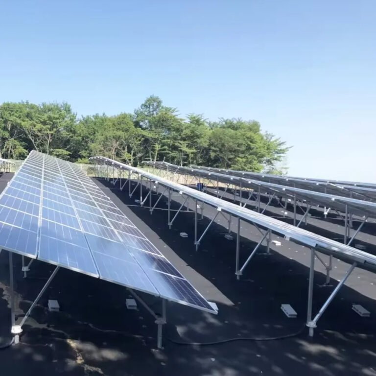
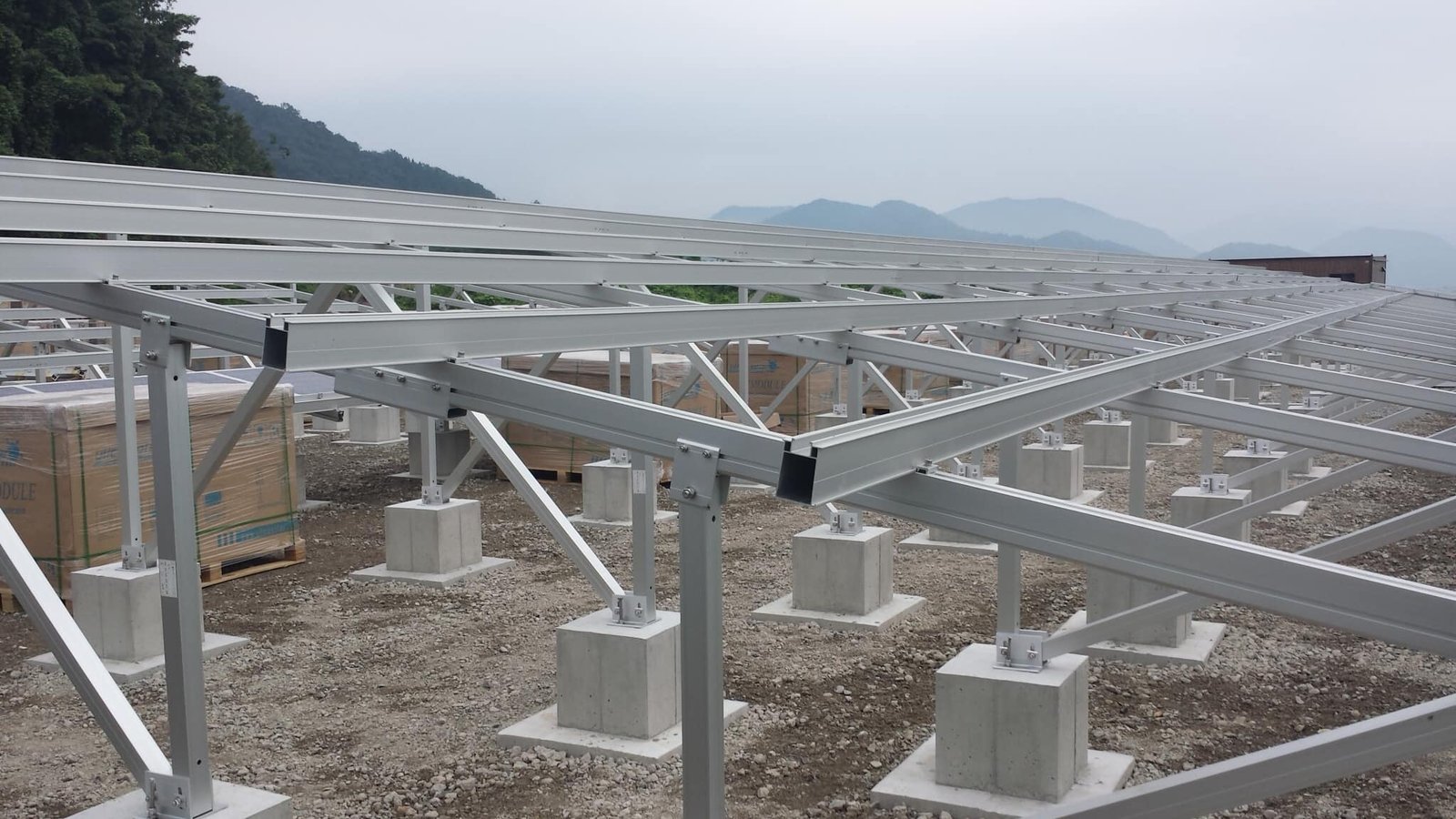
| Galvanized Steel Racks | High strength, 25-year lifespan | Heavy weight, high transport costs | Large ground-mounted systems |
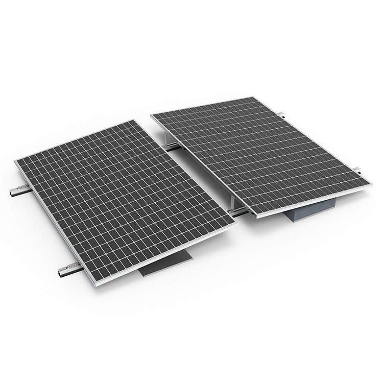
| Aluminum Racks | Lightweight, corrosion-resistant | High cost, lower load capacity | Rooftop distributed systems |
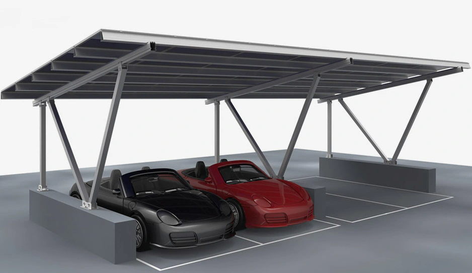
| Concrete Ballast Blocks | No need for foundation, quick installation | Poor wind resistance | Flat, hardened ground surfaces |
Chosen System: Galvanized Steel Racks (C-steel Q235B)
Reason: Lower cost, strong wind resistance.
3. Load Calculations
3.1 Dead Load (G)
- Module weight: 28.5 kg/piece × 20 pieces = 570 kg → 5.6 kN
- Rack weight: Estimated at 12 kg/m² → 1.2 kN
3.2 Live Load (Q)
- Wind Load (W): According to GB50009, Wk=βzμsμzW0W_k = \beta_z \mu_s \mu_z W_0
Where:- βz\beta_z (wind vibration coefficient) = 1.0
- μs\mu_s (shape factor) = 1.3 (for 25° module tilt)
- μz\mu_z (wind pressure height factor) = 1.0 (at 10m height)
- W0W_0 (basic wind pressure) = 0.45 kN/m²
Result: Wk=0.59kN/m2W_k = 0.59 kN/m²
- Snow Load (S): 0.30 kN/m²×1.0 (slope factor)=0.30 kN/m²0.30 \, \text{kN/m²} \times 1.0 \, (\text{slope factor}) = 0.30 \, \text{kN/m²}
3.3 Load Combinations
| Combination Type | Formula | Calculation Result (kN/m²) |
|---|---|---|
| Dead Load + Live Load | 1.2G + 1.4Q | 1.2 × 6.8 + 1.4 × 0.59 = 9.23 |
| Dead Load + Wind Load | 1.0G + 1.4W | 6.8 + 1.4 × 0.59 = 7.63 |
Control Condition: Dead Load + Live Load Combination (9.23 kN/m²)
4. Structural Verification
4.1 Purlin Calculation
- Selected: C80×40×15×2.0 Galvanized C-Steel
- Span: 2.5 m
- Moment: M=qL28=9.23×1.2×2.528=8.66 kN\cdotpmM = \frac{qL^2}{8} = \frac{9.23 \times 1.2 \times 2.5^2}{8} = 8.66 \, \text{kN·m}
- Bending Check: σ=MWx=8.66×10620.5×103=422 MPa>235 MPa\sigma = \frac{M}{W_x} = \frac{8.66 \times 10^6}{20.5 \times 10^3} = 422 \, \text{MPa} > 235 \, \text{MPa} ❌
Conclusion: Does not meet the requirement! Use C100×50×20×2.5 (with Wx=34.2×103 mm3W_x = 34.2 \times 10^3 \, \text{mm}^3, σ=253 MPa\sigma = 253 \, \text{MPa})
4.2 Column Stability
- Selected: 80×80×3.0 Square Pipe
- Slenderness Ratio: λ=Li=250031.3=79.8<150\lambda = \frac{L}{i} = \frac{2500}{31.3} = 79.8 < 150 ✅
- Axial Force: N=9.23×2.5×1.2=27.69 kNN = 9.23 \times 2.5 \times 1.2 = 27.69 \, \text{kN}
- Stability Factor: ϕ=0.68\phi = 0.68 (from tables)
- Verification: NϕA=27.69×1030.68×913=44.6 MPa<215 MPa\frac{N}{\phi A} = \frac{27.69 \times 10^3}{0.68 \times 913} = 44.6 \, \text{MPa} < 215 \, \text{MPa} ✅
5. Material List and Cost Comparison
| Materiale | Galvanized Steel Option | Aluminum Option | Savings Ratio |
|---|---|---|---|
| Main Beam (tons) | 3.2 | 1.8 | -43% |
| Purlin (tons) | 1.5 | 0.9 | -40% |
| Total Cost (¥10,000) | 8.5 | 12.0 | +41% |
Conclusion: The galvanized steel option is more cost-effective, but purlin reinforcement needs attention.
6. Grounding and Design Suggestions
- Rust Prevention: Galvanized layer thickness ≥ 80μm, with anti-rust paint on welds.
- Water Drainage: Purlins should have drainage holes to avoid water accumulation.
- Quick Installation: Pre-drill holes and use bolts to minimize onsite welding.
Approval:
- Designer: ______
- Reviewer: ______
Notes:
Actual construction may need to adjust the foundation type based on site soil reports (recommended screw piles or concrete foundations).
Key Takeaways: Quantitative Evaluation Method for Material Selection
In solar mounting design, balancing cost e performance requires data-driven decision-making to avoid subjective errors or overdesign. Below is a method for quantitative evaluation, covering key indicators, calculation models, and real-world case studies.
- Establishing a Quantitative Evaluation Indicator System
Decompose cost and performance into measurable indicators, assigning weights based on project needs. - Key Parameter Quantification
Example: Wind Pressure Resistance vs. Material Cost
Case Comparison:- Q235B Galvanized Steel (Strength 235 MPa, Price ¥5000/ton)
- Q355B Galvanized Steel (Strength 355 MPa, Price ¥5800/ton)
- Aluminum 6061 (Strength 310 MPa, Price ¥25000/ton)
Conclusion: Q355B steel offers the best cost-performance ratio, with 51% higher strength and just a 16% price increase.
- Sensitivity Analysis
Identify variables with the most impact on cost and performance, such as wind pressure and corrosion levels. - Final Decision Making
Use weighted scoring to compare materials based on the calculated cost-effectiveness and performance.
Summary: A well-designed solar mounting system relies on understanding both the cost e performance of materials.
By using data and careful analysis, you can avoid overdesign, meet local environmental requirements, and ensure that your system lasts for decades.