-
2103 Room NO.322 Xinggang One Road, Haicang District, Xiamen Fujian, Chiny


Calculation of Spacing Between PV Arrays and Design Requirements for Solar Module Structures
Table of Contents
The design of solar module mounting structures must comprehensively consider factors such as load-bearing capacity, wind resistance, durability, ease of installation, material selection, adjustability, and seismic performance to ensure the performance and lifespan of the photovoltaic power system.
The support structure design should be determined based on local climate and meteorological data, module dimensions, installation and maintenance costs, energy yield, and grid feed-in tariffs. It must also account for the mechanical parameters of the modules and the maximum wind speed they can withstand.
In addition, the design must consider the latitude of the project location to determine the optimal tilt angle for the solar panels, as different tilt angles result in different monthly energy outputs.
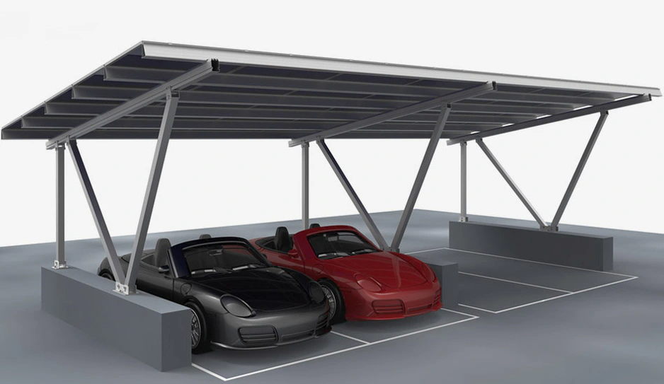
Common mounting structure types include fixed-tilt systems, single-axis tracking systems, and dual-axis tracking systems. Materials commonly used include steel profiles, aluminum alloy profiles, or a combination of both.
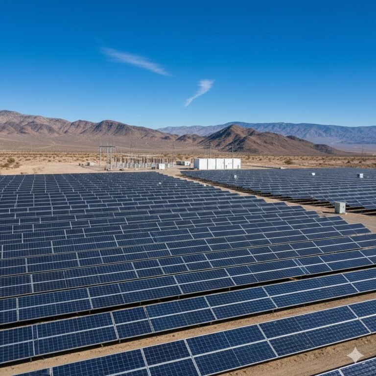
Below is a discussion focused on fixed-tilt systems using steel profiles:

Design Principles:
- Maximize annual energy production
- Structural design lifespan of 50 years
- Wind load: 35 m/s
- PV array foundations use isolated footings
- Material: Q235 hot-rolled steel
Tilt Angle Design:
Tilt angle design is generally aided by specialized software. The optimal tilt angle is determined by minimizing system losses through angle adjustments.
Array Spacing Calculation:
The calculation of the minimum spacing between PV arrays mainly depends on geographical location, solar movement, and the mounting structure height.
Formula 1 – Minimum spacing between arrays or between an array and potential shading objects (vertical distance from the bottom of the array):

- D – Minimum spacing between PV arrays or from the bottom edge of the array to the nearest shading object (in vertical projection)
- Φ – Latitude (positive in the Northern Hemisphere, negative in the Southern Hemisphere)
- H – Vertical height difference between the top of the PV array (or obstacle) and the bottom edge of the shaded module
This formula applies to locations with latitude ≤ 45°. In areas with latitude > 45°, the value of D may be slightly reduced, but should not be less than the value at 45° latitude.
Formula 2 – Ensuring no mutual shading among PV arrays:

To determine the minimum spacing:
- φ – Latitude
- δ – Solar declination angle (−23.5° at winter solstice)
- ω – Hour angle, typically 45° at 9:00 AM
- L – Array spacing
- H – Array height = module length × sin(optimal tilt angle)
Formula 3 – Spacing calculations for rooftop PV installations:
- Flat roof, north-south array layout – projection spacing between the lowest points of two consecutive arrays:

- D₀ – Distance between two rows of PV arrays (m)
- L – Length of the PV module (m)
- β – Tilt angle of the PV module (°)
- Φ – Latitude of the project location
- Flat roof, north-south layout – net spacing between the highest point of the front array and the lowest point of the rear array (clearance distance):

- d – Net clearance between two rows of PV arrays (m)
- L – PV module length (m)
- β – Tilt angle (°)
- Φ – Latitude of the project location
- Spacing between PV arrays and parapet walls or shading objects:

See diagram (not shown here)

- D – Minimum distance between PV array and parapet wall or shading object
- H – Vertical distance from the highest to the lowest point of the PV array
- h – Vertical distance between the top of the parapet wall or shading object and the lowest point of the PV module
- aₛ – Solar altitude angle
- β – Acute angle between the parapet wall (or shading object) and true east/west direction
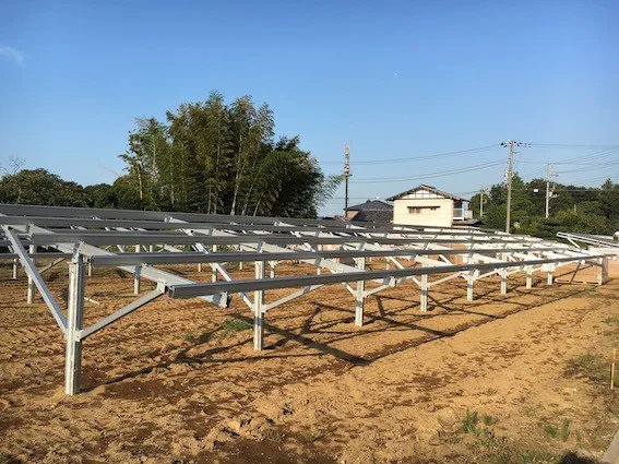
4. Structural Design of the Mounting System:
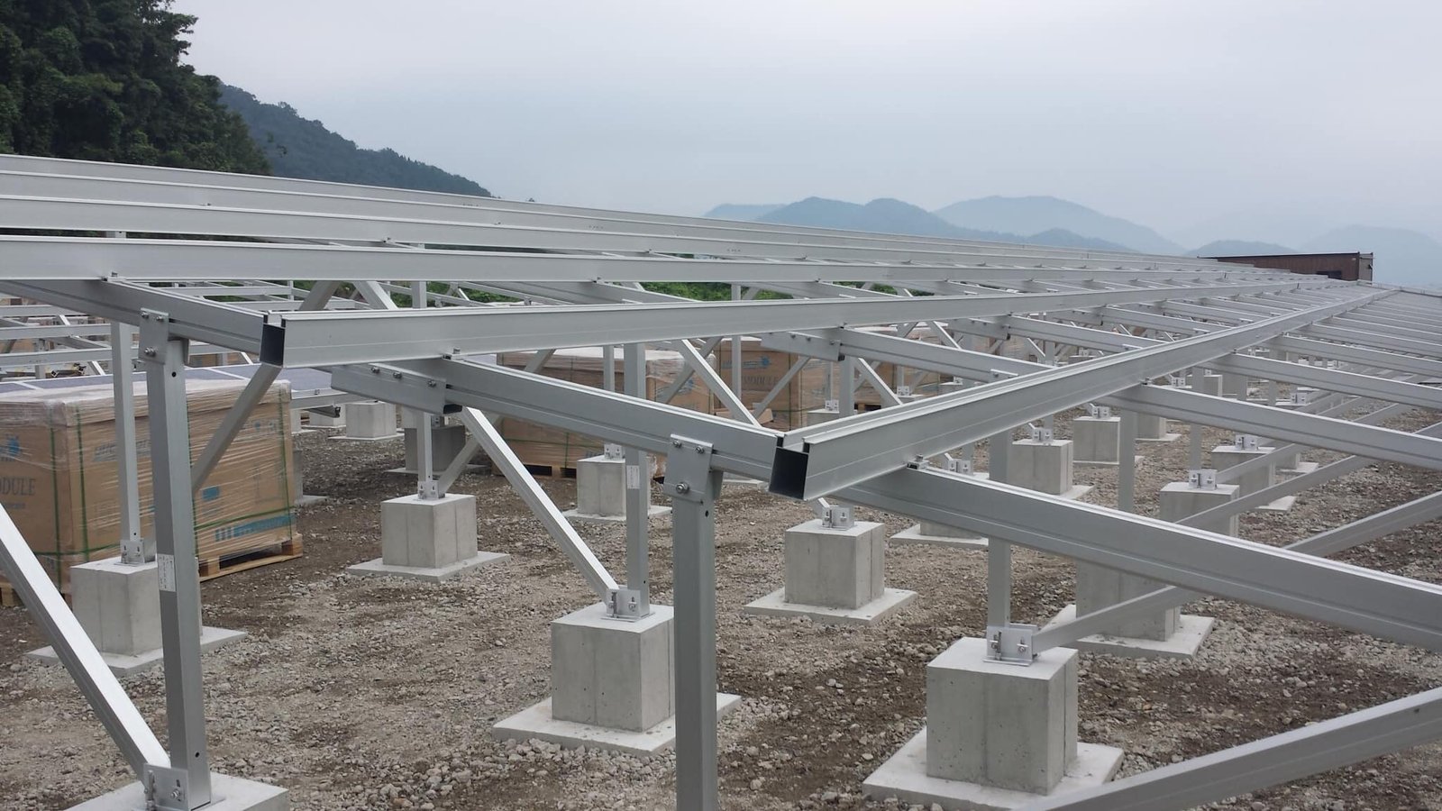
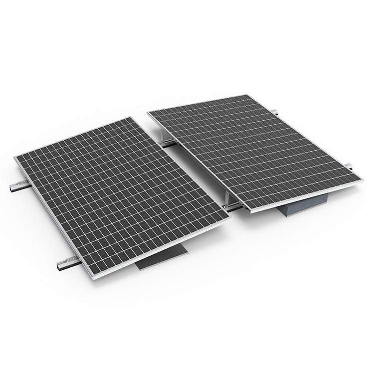
The PV module mounting structure uses steel profiles with hot-dip galvanization. The components are fastened with bolts, and a 5 cm wind deflector is provided to ensure structural stability.
For fixed-tilt systems, the typical design includes:
- Cold-formed equal-angle channel steel installed along the module’s short side (mounting hole side) and bolted to the module.
- The channel steel is mounted on a triangular bracket made of cold-formed equal-angle channel steel.
- The main beam is bolted to front and rear vertical posts for easy construction.
- Vertical posts are anchored to foundations using pre-embedded M20 anchor bolts.
This configuration forms a complete structural system with sufficient strength and rigidity. All steel components are galvanized to enhance durability. The structural design should include detailed calculations based on module dimensions and support structure parameters, including wind load analysis and structural stability checks. Further discussion on this aspect can be pursued when needed.